The Workshop
Notes from the workbench: microcontroller sketches for Arduino, Netduino and chipKit boards, mostly worked through from the Arduino Cookbook (2nd ed.) by Michael Margolis and the Digilent examples, with a Bus Pirate and a scope close at hand. Code is included; click any project to expand it.
RGB LED Projekte
Das Erste! Written up in German. The starting point was the Adafruit RGB LED lesson. Blue is on pin 5, green on pin 6 and red on pin 7, with a common-cathode LED.
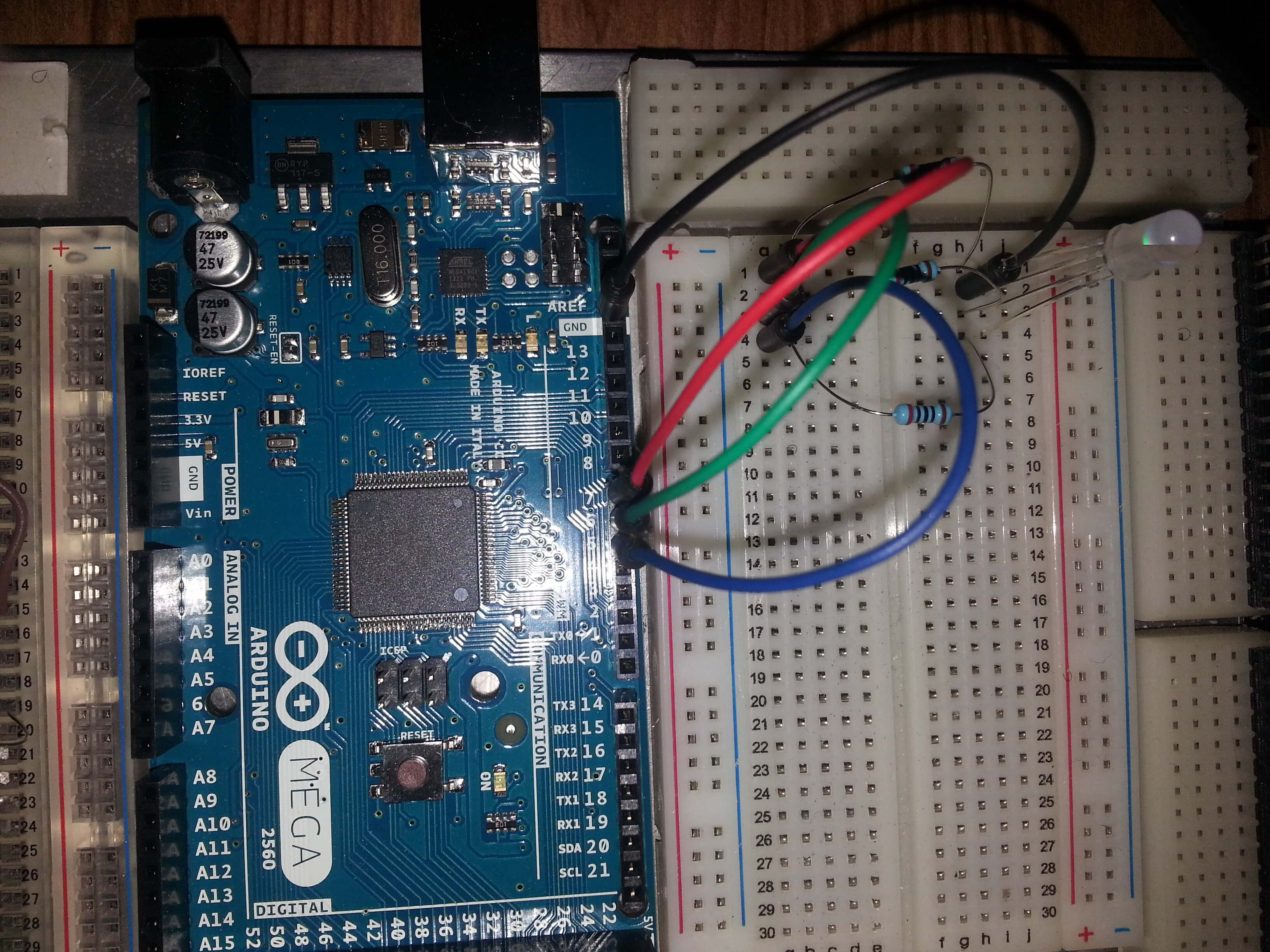
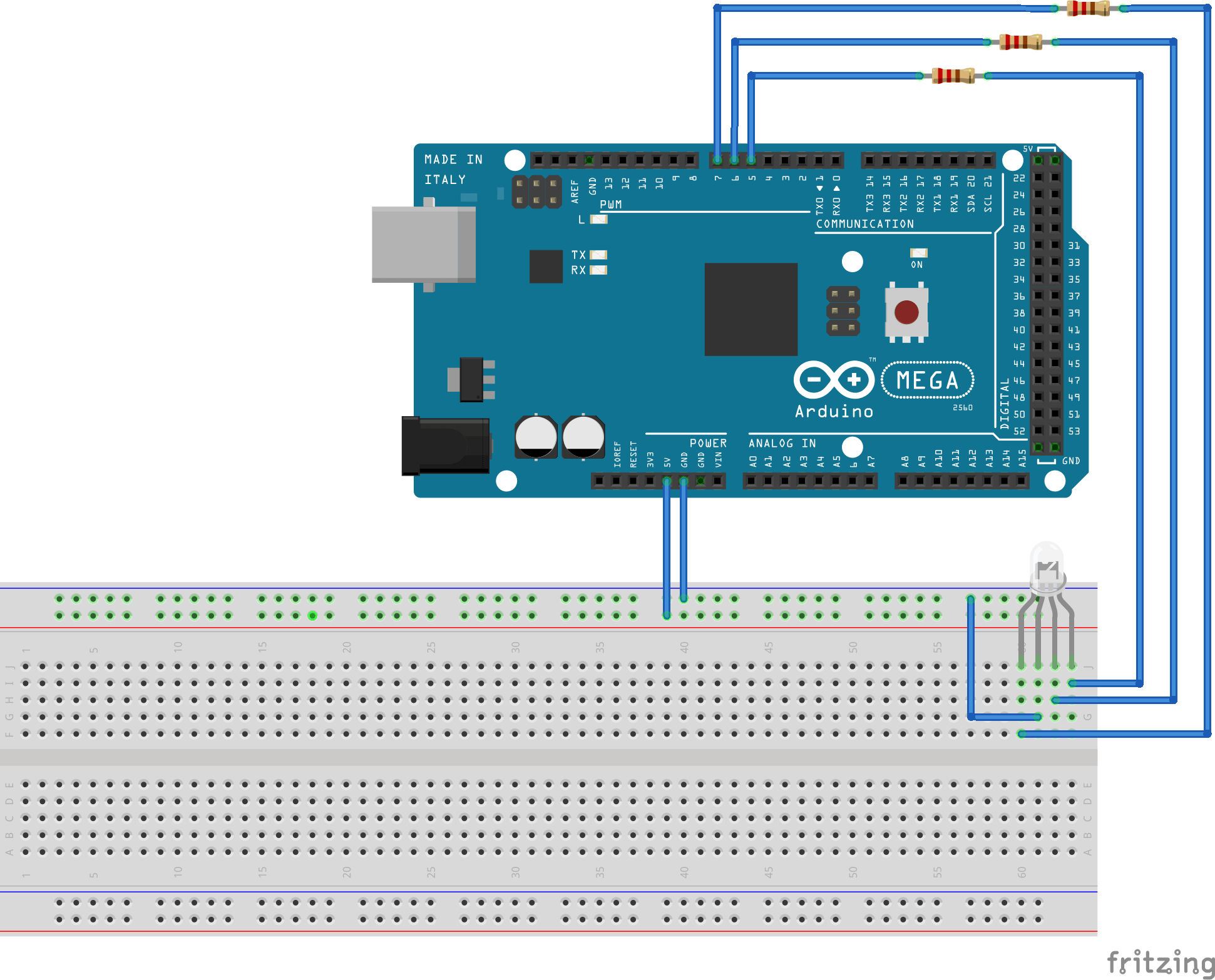
rgb_led_continuous · cycles through the colors
int rot_pin = 5;
int gruen_pin = 6;
int blau_pin = 7;

// common cathode

void setup()
{
   pinMode(rot_pin,OUTPUT);
   pinMode(gruen_pin,OUTPUT);
   pinMode(blau_pin,OUTPUT);
}

void loop()
{
   //setColor(255,0,0);
   //delay(1000);
   for (int n=0; n<8; n++) {
     for (int x=0; x<8; x++) {
       for (int y=0; y<16; y++) {
         setColor(16*n,255-16*x,0);
         delay(1);
       }
     }
   }
   setColor(0,0,10);
   delay(5000);
}

void setColor(int rot, int gruen, int blau)
{
   analogWrite(rot_pin,rot);
   analogWrite(gruen_pin,gruen);
   analogWrite(blau_pin,blau);
}
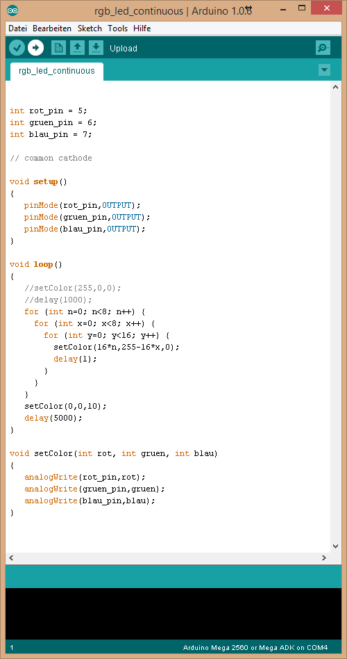
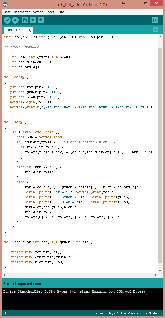
rgb_led_ask · type R,G,B values in the serial monitor
int rot_pin = 7; int gruen_pin = 6; int blau_pin = 5;

// common cathode

   int rot; int gruen; int blau;
   int field_index = 0;
   int colors[3];

void setup()
{
   pinMode(rot_pin,OUTPUT);
   pinMode(gruen_pin,OUTPUT);
   pinMode(blau_pin,OUTPUT);
   Serial.begin(19200);
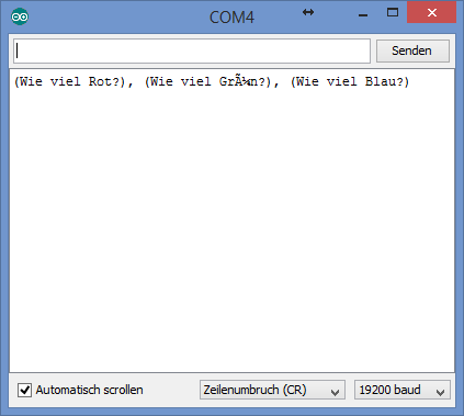
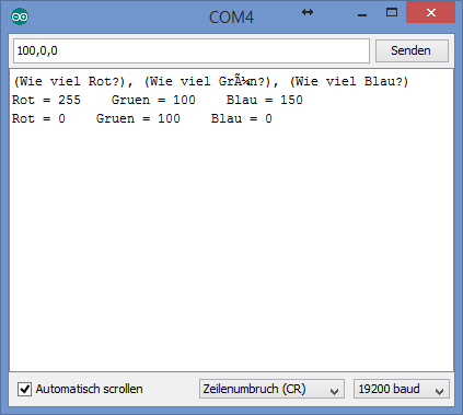
   Serial.println("(Wie viel Rot?), (Wie viel Grün?), (Wie viel Blau?)");
}

void loop()
{
    if (Serial.available()) {
      char num = Serial.read();
      if (isDigit(num)) { // is ascii between 0 and 9?
        if(field_index < 3) {
          colors[field_index] = (colors[field_index] * 10) + (num - '0');
        }
      }
      else if (num == ',') {
          field_index++;
      }
      else {
          rot = colors[0];  gruen = colors[1];  blau = colors[2];
          Serial.print("Rot = ");  Serial.print(rot);
          Serial.print("    Gruen = ");   Serial.print(gruen);
          Serial.print("    Blau = ");   Serial.println(blau);
          setColor(rot,gruen,blau);
          field_index = 0;
          colors[0] = 0;  colors[1] = 0;  colors[2] = 0;
      }
    }
}

void setColor(int rot, int gruen, int blau)
{
   analogWrite(rot_pin,rot);
   analogWrite(gruen_pin,gruen);
   analogWrite(blau_pin,blau);
}
Debouncing & serial ports
Input/output and serial communications from Chapters 4 and 5 of the Arduino Cookbook, carried a bit further. Lots of fun.
Switch debouncing, carried further
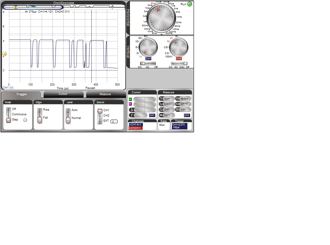
Based on Cookbook 5.2–5.4. The internal pull-up means no resistor is needed. It measures how long the button bounces and how long it's held, and reports both over serial. I had some trouble with stupidity in programming, then took the scope photo.
Debounce sketch
const int led_pin = 13;
const int input_pin = 2;    // switch input
const int debounce_delay = 10;
const int program_cycle_pin = 10
int bounce_count = 0;
int pb_on = 0;   // time from 1st pb press
int pb_bounce = 0;  //total bounce time
int pb_press = 0;
boolean pb_bounce_end = 0;

void setup() {
  pinMode(led_pin,OUTPUT);
  pinMode(input_pin,INPUT);
  digitalWrite(input_pin,HIGH);  // turns on internal pull-up R
  Serial.begin(19200);
  delay(100);
}

void loop() {
  digitalWrite(program_cycle_pin,HIGH);
  int pb_val = digitalRead(input_pin);
  //Serial.print("beg loop ");
  //Serial.print(pb_val); Serial.print(" "); Serial.print(pb_on); Serial.print(" "); Serial.println(pb_press);
  if (pb_val == HIGH) {
    digitalWrite(led_pin,LOW);  // pb off
    bounce_count = 0;
    if (pb_press == 1) {
    pb_on++;
    pb_bounce++;
    }
    if (pb_bounce_end  == 1) {
      //Serial.print("HI");
      pb_on = 0;
      pb_bounce_end = 0;
      pb_bounce = 0;
      pb_press = 0;
     delay(1000);  // need to figure better way to get let go bounce time
    }
  }
  else {
    digitalWrite(led_pin,HIGH);  // pb pressed
    pb_press = 1;
    pb_on++;
    pb_bounce++;
    bounce_count++;
  }
  //Serial.print("end loop ");
  //Serial.print(pb_on); Serial.print(" "); Serial.println(bounce_count);
  if (bounce_count == 10) {
    Serial.print("Debounce Delay "); Serial.print(debounce_delay); Serial.println(" msec");
    Serial.print("PB Bounce for "); Serial.print(pb_bounce); Serial.println(" msec");
    Serial.print("PB ON for "); Serial.print(pb_on); Serial.println(" msec");
    Serial.print("\n");
    pb_bounce_end = 1;
  }
  if (pb_on == 1000) {
    Serial.print("PB ON for "); Serial.print(pb_on); Serial.println("msec");
  }
  digitalWrite(program_cycle_pin,LOW);
  delay(1);
}
Serial port projects
1. Serial port monitor · changed to 19200 baud, one line per second
void setup() {
 Serial.begin(19200);
}

int number = 0;

void loop() {
  Serial.print("The number is ");
  Serial.println(number);
  delay(1000);
  number++;
}
2. ASCII table · formatting had to live in loop(), not setup()
void setup() {
  Serial.begin(19200);
  Serial.print("ASCII   Dec   Hex   Oct     Bin");
  Serial.println();
}

  int ascii_char = 33;

void loop() {
  //Serial.print("ASCII   Dec   Hex   Oct    Bin");
  //Serial.print("Character is : ");
  Serial.print("  ");
  Serial.write(ascii_char);
  //Serial.print("  Decimal is : ");
  Serial.print("      ");
  Serial.print(ascii_char,DEC);
  //Serial.print("  Hex is : ");
  Serial.print("    ");
  Serial.print(ascii_char,HEX);
  //Serial.print("  Octal is : ");
  Serial.print("    ");
  Serial.print(ascii_char,OCT);
  //Serial.print("  Binary is : ");
  Serial.print("   ");
  Serial.print(ascii_char,BIN);
  Serial.println();
  ascii_char++;
  delay(1000);
}
3. Blink the LED from the PC · type 0–9, blink rate is number × 100 ms
int led = 13;
int blink_rate = 0;

void setup() {
  Serial.begin(19200);
  pinMode(led,OUTPUT);
}

void loop() {
  if (Serial.available()) {
    char num = Serial.read();
    if (isDigit(num)) { // is ascii between 0 and 9?
        blink_rate = (num - '0') * 100;
    }
  }
  blink();
}

// blink routine
void blink() {
  digitalWrite(led,HIGH);
  delay(blink_rate);
  digitalWrite(led,LOW);
  delay(blink_rate);
}
4. Blink rate in milliseconds · PuTTY sends 0xD, not 0xA, so the sketch now expects CR
int led = 13;
int blink_rate = 0;
int num_value;

void setup() {
  Serial.begin(19200);
  pinMode(led,OUTPUT);
}

void loop() {
  if (Serial.available()) {
    char num = Serial.read();
    Serial.print(num,HEX);
    Serial.print(" ");
    if (isDigit(num)) { // is ascii between 0 and 9?
      num_value = (num_value * 10) + (num - '0');
    }
    else if (num == 13) {  // newline?
      blink_rate = num_value;
      Serial.println(blink_rate);
      num_value = 0;
    }
  }
  blink();
}

// blink routine
void blink() {
  digitalWrite(led,HIGH);
  delay(blink_rate);
  digitalWrite(led,LOW);
  delay(blink_rate);
}
5. Send header + sensor values to the PC · Cookbook 4.4
int value1 = 10; // some hardcoded values to send
int value2 = 100;
int value3 = 1000;
void setup() {
  Serial.begin(19200);
}

void loop() {
  Serial.print('H'); // unique header to identify start of message
  Serial.print(",");
  Serial.print(value1,DEC);
  Serial.print(",");
  Serial.print(value2,DEC);
  Serial.print(",");
  Serial.print(value3,DEC);
  Serial.print(","); // note that a comma is sent after the last field
  Serial.println(); // send a cr/lf
  delay(100);
  value1++;
  value2++;
  value3++;
}
6. Processing: read the serial port · 19200 baud, pick the right COM port index
// Processing Sketch to read comma delimited serial
// expects format: H,1,2,3,
import processing.serial.*;
Serial myPort; // Create object from Serial class
char HEADER = 'H'; // character to identify the start of a message
short LF = 10; // ASCII linefeed
// WARNING!
// If necessary change the definition below to the correct port
short portIndex = 1; // select the com port, 0 is the first port
void setup() {
  size(200, 200);
  println(Serial.list());
  println(" Connecting to -> " + Serial.list()[portIndex]);
  myPort = new Serial(this,Serial.list()[portIndex], 19200);
}
void draw() {
}
void serialEvent(Serial p)
{
  String message = myPort.readStringUntil(LF); // read serial data
  if(message != null)
  {
    print(message);
    String [] data = message.split(","); // Split the comma-separated message
    if(data[0].charAt(0) == HEADER && data.length > 3) // check validity
    {
      for( int i = 1; i < data.length-1; i++) // skip the header & end if line
      {
        println("Value " + i + " = " + data[i]); // Print the field values
      }
      println();
    }
  }
}
7. Processing: display the Arduino's analog inputs
import processing.serial.*;

Serial myPort;
String message = null;
int font_size = 12;

int max_num_labels = 12;

int rect_margin = 40;
int window_width = 600;
int window_height = rect_margin + (max_num_labels + 1) * (font_size * 2);
int rect_width = window_width - (rect_margin * 2);
int rect_height = window_height -rect_margin;
int min_value = 0;
int max_value = 255;
int origin = rect_margin;
float scale = float(rect_width) / (max_value - min_value);
String [] sensor_labels = {"s1","s2","s3","s4","s5","s6","s7","s8","s9","s10","s11","s12"};
int label_count = max_num_labels;


short LF = 10; // ASCII linefeed


void setup() {
  size(window_width, window_height);
   short port_index = 1; // select the com port, 0 is the first port
  String port_name = Serial.list()[port_index];
  println(Serial.list());
  println(" Connecting to -> " + port_name);
  myPort = new Serial(this,port_name, 19200);
}


void drawGrid() {
  fill(0);
  text(min_value,xPos(min_value),rect_margin - font_size);
  line(xPos(min_value),rect_margin + font_size,xPos(min_value),rect_height + font_size);


  text(max_value,xPos(max_value),rect_margin - font_size);
  line(xPos(max_value),rect_margin,xPos(max_value),rect_height + font_size);

  for (int i=0;i<label_count;i++) {
    text(sensor_labels[i],font_size,yPos(i));
    text(sensor_labels[i],xPos(max_value) + font_size,yPos(i));
  }
}
int yPos(int index) {
  return rect_margin + font_size + (index * font_size * 2);
}
int xPos(int value) {
  return origin + int(scale * value);
}

void drawBar(int yIndex,int value) {
  rect(origin,yPos(yIndex) - font_size,value*scale,font_size);
}

void draw() {
  while (myPort.available () > 0) {
    try {
      message = myPort.readStringUntil(LF);  //read until find LF
      if (message != null) {
        print(message);
        String [] data = message.split(",");
        if (data[0].equals("Labels")) {  //Label header?
          label_count = min(data.length - 1,max_num_labels);
          arrayCopy(data,1,sensor_labels,0,label_count);
        }
        else if (data[0].equals("Data")) {  //Data header?
          background(#00ffff);
          drawGrid();
          fill(#ff00aa);
          println(data.length);
          for (int i=1;i<=label_count && i < data.length - 1;i++) {
            drawBar(i - 1,Integer.parseInt(data[i]));
          }
        }
      }
    }
    catch (Exception e) {
      e.printStackTrace();  //display error
    }
  }
}
8. Arduino stimulus for the analog display
void setup() {
  Serial.begin(19200);
  delay(1000);
  Serial.println("Labels,L0,L1,L2,L3,L4,L5");
}

void loop() {
  Serial.print("Data,");
  for(int i=0;i<6;i++) {
    Serial.print(analogRead(i));
    Serial.print(",");
  }
  Serial.print('\n');
  delay(100);
}
9. Processing: move the PC mouse from the Arduino · Cookbook 4.10, updated for newer Processing
// use esc to stop sketch

import java.awt.AWTException;
import java.awt.Robot;
import processing.serial.*;

Serial myPort;  //creates object from Serial class
arduMouse myMouse;  //creates arduino controlled mouse

public static final short LF = 10;
public static final short port_index = 1;  //com port, 0 is first

int posX, posY, btn;  //data from message fields

void setup() {
  size(200, 200);
  println(Serial.list());
  println(" Connecting to -> " + Serial.list()[port_index]);
  myPort = new Serial(this,Serial.list()[port_index], 19200);
  myMouse = new arduMouse();
  btn = 0;  //mouse off for now
}

void draw() {
  if (btn != 0)
    myMouse.move(posX,posY);
}

void serialEvent(Serial p) {
  String message = myPort.readStringUntil(LF); // read serial data
  if(message != null) {
    print(message);
    String [] data = message.split(","); // Split the comma-separated message
    if(data[0].equals("Data")) {// check validity
      if (data.length > 3) {
        try {
          posX = Integer.parseInt(data[1]);
          posY = Integer.parseInt(data[2]);
          btn  = Integer.parseInt(data[3]);
        }
        catch (Throwable t) {
          println(".");  //parse error
          print(message);
        }
      }
    }
  }
}

class arduMouse {
  Robot myRobot;  //create Robot class object

  static final short rate = 1;  //multiplier for movement rate
  int centerX, centerY;
  arduMouse() {
    try {
      myRobot = new Robot();
    }
    catch (AWTException e) {
      e.printStackTrace();
    }

    //screen = java.awt.Toolkit.getDefaultToolkit().size();
    //size(displayWidth,displayHeight); //creates big box
    centerX = (int)width/2;  //displayWidth not needed as variable?
    centerY = (int)height/2;
    print("width = " + width + " height = " + height);
  }
  void move(int offsetX,int offsetY) {
      myRobot.mouseMove(rate * offsetX,rate * offsetY);  //didn't like center as origin, probably should change
  //  myRobot.mouseMove(centerX + (rate * offsetX),centerY - (rate * offsetY));
    //println(offsetX + " " + offsetY);
  }
}
10. Arduino stimulus: sweep x 1–1920, y 1–1080
  int value1 = 1; // some hardcoded values to send
  int value2 = 1;
  int value3 = 1;
  void setup() {
  Serial.begin(19200);
}

void loop() {
  Serial.print("Data"); // unique header to identify start of message
  Serial.print(",");
  Serial.print(value1,DEC);
  Serial.print(",");
  Serial.print(value2,DEC);
  Serial.print(",");
  Serial.print(value3,DEC);
  Serial.print(","); // note that a comma is sent after the last field
  Serial.println(); // send a cr/lf
  delay(100);
  value1 = value1 + 10;
  if (value1 > 1920) {
    value1 = 1;
  }
  value2 = value2 + 10;
  if (value2 > 1080) {
    value2 = 1;
  }
  //value3++;
}
Netduino projects
The same beginner exercises, this time in C#.
Blinky Onboard
Blink the onboard LED. Hello, World!
Code
using System;
using System.Net;
using System.Net.Sockets;
using System.Threading;
using Microsoft.SPOT;
using Microsoft.SPOT.Hardware;
using SecretLabs.NETMF.Hardware;
using SecretLabs.NETMF.Hardware.NetduinoPlus;


namespace NetduinoPlusApplication1
{
    public class Program
    {
        public static void Main()
        {
            OutputPort led = new OutputPort(Pins.ONBOARD_LED, false);
            while (true)
            {
                led.Write(true);
                Thread.Sleep(250);
                led.Write(false);
                Thread.Sleep(250);
            }
        }

    }
}Blinky Pins
Blink both the onboard and an external LED, alternating.
Code
using System;
using System.Net;
using System.Net.Sockets;
using System.Threading;
using Microsoft.SPOT;
using Microsoft.SPOT.Hardware;
using SecretLabs.NETMF.Hardware;
using SecretLabs.NETMF.Hardware.NetduinoPlus;

namespace NetduinoPlusApplication1
{
    public class Program
    {
        public static void Main()
        {
            OutputPort blu_led = new OutputPort(Pins.GPIO_PIN_D0, false);
            OutputPort led = new OutputPort(Pins.ONBOARD_LED, false);

            while (true)
            {
                led.Write(true);
                blu_led.Write(false);
                Thread.Sleep(250);

                led.Write(false);
                blu_led.Write(true);
                Thread.Sleep(250);
            }
        }

    }
}Blinky Button
Use the onboard button to switch the blinking pattern of two LEDs.
Code
using System;
using System.Net;
using System.Net.Sockets;
using System.Threading;
using Microsoft.SPOT;
using Microsoft.SPOT.Hardware;
using SecretLabs.NETMF.Hardware;
using SecretLabs.NETMF.Hardware.NetduinoPlus;

namespace NetduinoPlusApplication1
{
    public class Program
    {
        public static void Main()
        {
            OutputPort led = new OutputPort(Pins.ONBOARD_LED, false);
            OutputPort blu_led = new OutputPort(Pins.GPIO_PIN_D0, false);
            InputPort button = new InputPort(Pins.ONBOARD_SW1, false, Port.ResistorMode.Disabled);
            bool buttonState = false;

            while (true)
            {
                buttonState = button.Read();
                Debug.Print(buttonState.ToString());

                led.Write(buttonState);
                blu_led.Write(!buttonState);
                Thread.Sleep(500);

                led.Write(!buttonState);
                blu_led.Write(buttonState);
                Thread.Sleep(250);
            }
        }

    }
}Blinky Potentiometer
Use a pot to control the LED blinking frequency.
Code
using System;
using System.Net;
using System.Net.Sockets;
using System.Threading;
using Microsoft.SPOT;
using Microsoft.SPOT.Hardware;
using SecretLabs.NETMF.Hardware;
using SecretLabs.NETMF.Hardware.NetduinoPlus;

namespace NetduinoPlusApplication1
{
    public class Program
    {
        public static void Main()
        {
            OutputPort blu_led = new OutputPort(Pins.GPIO_PIN_D0, false);
            //AnalogInput pot = new Microsoft.SPOT.Hardware.AnalogInput(SecretLabs.NETMF.Hardware.NetduinoPlus.AnalogChannels.ANALOG_PIN_A0);
            AnalogInput pot = new AnalogInput(AnalogChannels.ANALOG_PIN_A0);
            int pot_value = 0;

            while (true)
            {
                pot_value = (int) (pot.Read() * 255);
                Debug.Print(pot_value.ToString());
                Debug.Print(pot.Read().ToString());

                blu_led.Write(false);
                Thread.Sleep(pot_value);

                blu_led.Write(true);
                Thread.Sleep(pot_value);
            }
        }

    }
}LED Dimmer
A pot sets the duty cycle of a PWM port to dim the LED.
Code
using System;
using System.Net;
using System.Net.Sockets;
using System.Threading;
using Microsoft.SPOT;
using Microsoft.SPOT.Hardware;
using SecretLabs.NETMF.Hardware;
using SecretLabs.NETMF.Hardware.NetduinoPlus;

namespace NetduinoPlusApplication1
{
    public class Program
    {
        public static void Main()
        {
            PWM blue_led = new PWM(PWMChannels.PWM_PIN_D5, 100, 50, false);
            AnalogInput pot = new AnalogInput(AnalogChannels.ANALOG_PIN_A0);
            double pot_value = 0;

            while (true)
            {
                pot_value = pot.Read();
                Debug.Print(pot_value.ToString());
                Debug.Print(pot.Read().ToString());

                blue_led.DutyCycle = pot_value;
                //blue_led.DutyCycle = .9;
            }
        }

    }
}RGB LED
Random-ish RGB color patterns. Change the sleep time to make it less annoying; next time, a larger resistor!
Code
using System;
using System.Net;
using System.Net.Sockets;
using System.Threading;
using Microsoft.SPOT;
using Microsoft.SPOT.Hardware;
using SecretLabs.NETMF.Hardware;
using SecretLabs.NETMF.Hardware.NetduinoPlus;

namespace NetduinoPlusApplication1
{
    public class Program
    {
        public static void Main()
        {
            PWM red_led = new PWM(PWMChannels.PWM_PIN_D9, 100, 50, false);
            PWM green_led = new PWM(PWMChannels.PWM_PIN_D10, 100, 50, false);
            PWM blue_led = new PWM(PWMChannels.PWM_PIN_D6, 100, 50, false);

            double red_duty_cycle = 5;
            double green_duty_cycle = 11;
            double blue_duty_cycle = 19;

            int color_count = 1;

            while (true)
            {
                ++color_count;

                red_duty_cycle += color_count;
                if (red_duty_cycle > 50) { red_duty_cycle = 5; }
                red_led.DutyCycle += blue_duty_cycle / 100;

                green_duty_cycle += color_count;
                if (green_duty_cycle > 50) { green_duty_cycle = 1; }
                green_led.DutyCycle = green_duty_cycle / 100;

                blue_duty_cycle += color_count;
                if (blue_duty_cycle > 50) { blue_duty_cycle = 2; }
                blue_led.DutyCycle = blue_duty_cycle / 100;

                Debug.Print("color_count = " + color_count.ToString());
                Debug.Print("red = " + red_duty_cycle.ToString());
                Debug.Print("green = " + green_duty_cycle.ToString());
                Debug.Print("blue = " + blue_duty_cycle.ToString());
                Debug.Print(" ");

                if (color_count > 20) { color_count = 1; }

                Thread.Sleep(3000);
            }
        }

    }
}
chipKit projects
Adapted from Digilent's examples. When the libraries fought back, I wrote the I2C calls inline and watched the bus with a Bus Pirate.
Basic I/O LEDs
Pin numbers for all eight shield LEDs, blinking in alternation.
Code
/*
  Blink
  Turns on an LED on for one second, then off for one second, repeatedly.

  This example code is in the public domain.
 */
int ld1 = 77;
int ld2 = 76;
int ld3 = 75;
int ld4 = 74;
int ld5 = 73;
int ld6 = 72;
int ld7 = 71;
int ld8 = 70;
void setup() {
  // initialize the digital pin as an output.
  // Pin PIN_LED1 has an LED connected on most Arduino and compatible boards:
  pinMode(PIN_LED1, OUTPUT);
  pinMode(ld1, OUTPUT);
  pinMode(ld2, OUTPUT);
  pinMode(ld3, OUTPUT);
  pinMode(ld4, OUTPUT);
  pinMode(ld5, OUTPUT);
  pinMode(ld6, OUTPUT);
  pinMode(ld7, OUTPUT);
  pinMode(ld8, OUTPUT);
}

void loop() {
  digitalWrite(PIN_LED1, HIGH);   // set the LED on

  digitalWrite(ld1, LOW);    // set the LED off
  digitalWrite(ld3, LOW);    // set the LED off
  digitalWrite(ld5, LOW);    // set the LED off
  digitalWrite(ld7, LOW);    // set the LED off

  digitalWrite(ld2, HIGH);   // set the LED on
  digitalWrite(ld4, HIGH);   // set the LED on
  digitalWrite(ld6, HIGH);   // set the LED on
  digitalWrite(ld8, HIGH);   // set the LED on

  delay(1000);              // wait for a second

  digitalWrite(PIN_LED1, LOW);    // set the LED off

  digitalWrite(ld1, HIGH);   // set the LED on
  digitalWrite(ld3, HIGH);   // set the LED on
  digitalWrite(ld5, HIGH);   // set the LED on
  digitalWrite(ld7, HIGH);   // set the LED on

  digitalWrite(ld2, LOW);    // set the LED off
  digitalWrite(ld4, LOW);    // set the LED off
  digitalWrite(ld6, LOW);    // set the LED off
  digitalWrite(ld8, LOW);    // set the LED off

  delay(1000);              // wait for a second
}Basic I/O OLED
A basic message on the shield's OLED, plus the LEDs.
Code
#include <IOShieldOled.h>

int ld1 = 77;
int ld2 = 76;
int ld3 = 75;
int ld4 = 74;
int ld5 = 73;
int ld6 = 72;
int ld7 = 71;
int ld8 = 70;

void setup()
{
  IOShieldOled.begin();

  pinMode(PIN_LED1, OUTPUT);
  pinMode(ld1, OUTPUT);
  pinMode(ld2, OUTPUT);
  pinMode(ld3, OUTPUT);
  pinMode(ld4, OUTPUT);
  pinMode(ld5, OUTPUT);
  pinMode(ld6, OUTPUT);
  pinMode(ld7, OUTPUT);
  pinMode(ld8, OUTPUT);
}

void loop()
{
  int irow;
  int ib;

  //Clear the virtual buffer
  IOShieldOled.clearBuffer();

  //Chosing Fill pattern 0
  IOShieldOled.setFillPattern(IOShieldOled.getStdPattern(0));
  //Turn automatic updating off
  IOShieldOled.setCharUpdate(0);

  //Draw a rectangle over wrting then slide the rectagle
  //down slowly displaying all writing
  for (irow = 0; irow < IOShieldOled.rowMax; irow++)
  {
    IOShieldOled.clearBuffer();
    IOShieldOled.setCursor(0, 0);
    IOShieldOled.putString("Tom's chipKIT");
    IOShieldOled.setCursor(0, 1);
    IOShieldOled.putString("Basic I/O Shield");
    IOShieldOled.setCursor(0, 2);
    IOShieldOled.putString("by Digilent");

    IOShieldOled.moveTo(0, irow);
    IOShieldOled.drawFillRect(127,31);
    IOShieldOled.moveTo(0, irow);
    IOShieldOled.drawLine(127,irow);
    IOShieldOled.updateDisplay();
    delay(100);
  }

  delay(1000);

  // Blink the display a bit.
  IOShieldOled.displayOff();
  delay(500);
  IOShieldOled.displayOn();
  delay(500);

  IOShieldOled.displayOff();
  delay(100);
  IOShieldOled.displayOn();
  delay(100);

  //IOShieldOled.displayOff();
  //delay(500);
  //IOShieldOled.displayOn();
  //delay(500);

  delay(2000);

  // Now erase the characters from the display
  for (irow = IOShieldOled.rowMax-1; irow >= 0; irow--) {
    IOShieldOled.setDrawColor(1);
    IOShieldOled.setDrawMode(IOShieldOled.modeSet);
    IOShieldOled.moveTo(0,irow);
    IOShieldOled.drawLine(127,irow);
    IOShieldOled.updateDisplay();
    delay(25);
    IOShieldOled.setDrawMode(IOShieldOled.modeXor);
    IOShieldOled.moveTo(0, irow);
    IOShieldOled.drawLine(127, irow);
    IOShieldOled.updateDisplay();
  }

  delay(1000);

  // Draw a rectangle in center of screen
  // Display the 8 different patterns availible
  //IOShieldOled.setDrawMode(IOShieldOled.modeSet);

  //for(ib = 1; ib < 8; ib++)
  //{
    //IOShieldOled.clearBuffer();

    //IOShieldOled.setFillPattern(IOShieldOled.getStdPattern(ib));
    //IOShieldOled.moveTo(55, 1);
    //IOShieldOled.drawFillRect(75, 27);
    //IOShieldOled.drawRect(75, 27);
    //IOShieldOled.updateDisplay();

    //delay(1000);
  //}
  digitalWrite(ld1, LOW);    // set the LED off
  digitalWrite(ld3, LOW);    // set the LED off
  digitalWrite(ld5, LOW);    // set the LED off
  digitalWrite(ld7, LOW);    // set the LED off

  digitalWrite(ld2, HIGH);   // set the LED on
  digitalWrite(ld4, HIGH);   // set the LED on
  digitalWrite(ld6, HIGH);   // set the LED on
  digitalWrite(ld8, HIGH);   // set the LED on

  delay(1000);              // wait for a second

  digitalWrite(ld1, HIGH);   // set the LED on
  digitalWrite(ld3, HIGH);   // set the LED on
  digitalWrite(ld5, HIGH);   // set the LED on
  digitalWrite(ld7, HIGH);   // set the LED on

  digitalWrite(ld2, LOW);    // set the LED off
  digitalWrite(ld4, LOW);    // set the LED off
  digitalWrite(ld6, LOW);    // set the LED off
  digitalWrite(ld8, LOW);    // set the LED off

  delay(1000);              // wait for a second
}Temperature sensor
Had a bit of trouble: the I2C bus just hung. The culprit was probably a missing Wire.begin(), found with the Bus Pirate.
Code
//#include <IOShieldTemp.h>
#include <Wire.h>

#define ALERT_PIN 2
#define IOShieldTempAddr  0x48

int ld4 = 74;

void setup()
{
  Serial.begin(115200);
  Serial.println("Serial Port 115200");

  pinMode(ALERT_PIN, INPUT);

  pinMode(ld4, OUTPUT);

  byte error, address;
  Wire.begin();

  uint8_t temp[2] = {0};
  temp[0] = 0x01;
  temp[1] = 0xC4;
  Wire.beginTransmission(IOShieldTempAddr); // actual address, but need shift up and add r/w
  Wire.send(temp, 2);
  error = Wire.endTransmission();
  digitalWrite(ld4, HIGH);   // set the LED on
  delay(2000);
  Serial.print("error = ");
  Serial.println(error);
  if (error == 0){
      digitalWrite(ld4, LOW);   // set the LED on
  }

  //Set the range to bring the alert pin high if it's above 78F (25.5C), alert will stay
  //high until the temp drops below 75.2F (24C).
  //IOShieldTemp.setTempLimit(IOShieldTemp.convFtoC(78)); // 78.0F ~ 25.5C
  //IOShieldTemp.setTempHyst(24); // 75.2F ~ 24.0C
}

void loop()
{
  float tempF, tempC;


  //Get Temperature in Celsius.
  //tempC = IOShieldTemp.getTemp();
  float  tempResult;
  int16_t  wResult = 0;
  uint8_t temp[2] = {0};
  int index = 0;

  Wire.beginTransmission(IOShieldTempAddr);
  Wire.send(temp, 1);
  Wire.endTransmission();

  Wire.requestFrom(IOShieldTempAddr, 2);
  while(Wire.available())
  {
    temp[index++] = Wire.receive();
  }

  // Convert the result
  wResult = temp[1] | (temp[0] << 8);
  tempResult = wResult/256.0;

  // Convert the result to Fahrenheit.
  //tempF = IOShieldTemp.convCtoF(tempC);

  //
  tempC = tempResult;
  Serial.print(tempResult);
  Serial.print(" C, ");
  tempF = tempC*9.0/5.0+32.0;
  Serial.print(tempF);
  Serial.print(" F");
  Serial.println();

  delay(5000);
}EEPROM read/write
More library problems, so I made my own functions from theirs. Not sure they're correct, but it works.
Code
//#include <IOShieldEEPROM.h>
#include <Wire.h>

#define IOShieldEEPROMAddr  0x50

int ld4 = 74;

void setup() {

  char buf[26];
  char single;
  int i;

  pinMode(ld4, OUTPUT);

  Serial.begin(9600);
  Serial.println("Serial Port 9600");

  Wire.begin();

  //Write the alphabet to the EEPROM
  //The data length is assumed in this example because the data
  //is a string. If you write an array numbers to EEPROM then the
  //length of the array must be provided.
  //IOShieldEEPROM.writeString(0,"ABCDEFGHIJKLMNOPQRSTUVWXYZ");
  //char new_string = "ABCDEFGHIJKLMNOPQRSTUVWXYZ";
  //uint8_t data = new_string.toInt();
  writeString(0,"ABCDEFGHIJKLMNOPQRSTUVWXYZ",strlen("ABCDEFGHIJKLMNOPQRSTUVWXYZ"));
  digitalWrite(ld4, HIGH);   // set the LED on
  delay(2000);

  //Read alphabet back and print to monitor
  //IOShieldEEPROM.readString(0, buf, 26);
  readString(0, buf, 26);
  Serial.print(buf);
  Serial.println();

  //Write a single character
  write(20,'@');

  //Read all characters back
  readString(0, buf, 26);
  Serial.print(buf);
  Serial.println();

  //Read back last letter
  single = read(20);
  Serial.print(single);
}

void loop() {
  Serial.println("hello");
  delay(5000);
}

uint8_t read(uint16_t address) {
  char temp;
  readString(address, &temp, 1);
  return temp;
}

void write(uint16_t address, char data) {
  writeString(address, &data, 1);
}

void readString(uint16_t address, char *sz, int size) {
  uint8_t temp[2] = {0,0};
  int index = 0;
  temp[0] = (address >> 8);
  temp[1] = (address & 0xFF);

  Wire.beginTransmission(IOShieldEEPROMAddr);
  Wire.send(temp, 2);
  Wire.endTransmission();

  Wire.requestFrom(IOShieldEEPROMAddr, size);
  while(Wire.available()) {
  sz[index++] = Wire.receive();
  }
  //twi_writeTo(IOShieldEEPROMAddr, temp, 2, 1);
  //twi_readFrom(IOShieldEEPROMAddr, sz, size);
}

void writeString(uint16_t address, char *data, int size) {
  int i;
  uint8_t temp[67] = {0,0,0};
  temp[0] = (address >> 8);
  temp[1] = (address & 0xFF);

  if(size > 64) {
    size = 64;
  }

  for(i=0; i<size; i++) {
    temp[i+2] = *data;
    data++;
  }

  Wire.beginTransmission(IOShieldEEPROMAddr);
  Wire.send(temp, (size + 2));
  Wire.endTransmission();

  //twi_writeTo(IOShieldEEPROMAddr, temp, size+2, 1);
  delay(10);
}
I2C bus scanner
Marches through all 127 addresses. Used to test the Max32 bus when I thought it was broken.
Code
// i2c_scanner
 //
 // This program (or code that looks like it)
 // can be found in many places.
 // For example on the Arduino.cc forum.
 // The original author is not know.
 //
 // This sketch tests the standard 7-bit addresses
 // from 0 to 127. Devices with higher bit address
 // might not be seen properly.
 //
 // Adapted to be as simple as possible by Arduino.cc user Krodal
 //
 // June 2012
 // Using Arduino 1.0.1
 //

#include <Wire.h>

void setup()
 {
   Wire.begin();

  Serial.begin(115200);
   Serial.println("\nI2C Scanner");
 }

void loop()
 {
   byte error, address;
   int nDevices;

  Serial.println("Scanning...");

  nDevices = 0;
   for(address = 8; address <= 127; address++ )
  {
     // The i2c_scanner uses the return value of
     // the Write.endTransmisstion to see if
     // a device did acknowledge to the address.
     Wire.beginTransmission(address);
     error = Wire.endTransmission();

    if (error == 0)
     {
       Serial.print("I2C device found at address 0x");
       if (address<16)
        Serial.print("0");
       Serial.print(address,HEX);
       Serial.println(" !");

      nDevices++;
     }
     else if (error==4)
    {
       Serial.print("Unknow error at address 0x");
       if (address<16)
        Serial.print("0");
       Serial.println(address,HEX);
     }
   }
   if (nDevices == 0)
     Serial.println("No I2C devices found\n");
   else
     Serial.println("done\n");

  delay(8000);           // wait 8 seconds for next scan
 }
On the bench: a Rainbowduino LED matrix, a Raspberry Pi and an 8051. Write-ups to come, someday.